2D Space Planning only
$245/mon
The Fastest Interior Design Software for Stunning Home & Commercial Spaces. Design smarter, not harder! Foyr Neo is an AI-powered interior design software that transforms ideas into photorealistic 3D designs within minutes. Unlike traditional interior design programs, it requires zero learning curve and delivers fast, high-quality renders—all in your browser.
Try Free For 14 Days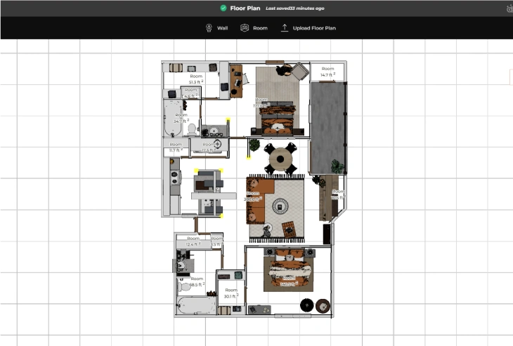
Using Foyr Neo's interior design software, you can go from idea to reality in minutes:

Best-in-class interior drawing software for detailed layouts.

Use 50,000+ furniture models inside our interior decorating software.

Showcase realistic designs with our interior design programs online.
Others Tools

2D Space Planning only
$245/mon

3D Modeling Software only
$25/mon

3D Rendering Software only
$235/mon

Hardware Upgrade Costs
3D modeling & rendering software typically need graphics (GPU) cards and more RAM.
One Tool To Complete Your Interior Design Projects

2D Space Planning
Upload & trace or create true-to-scale, high-quality, accurate floor plans within mins and export them in different formats.
Easily create & export elevations with custom measurement and text labels

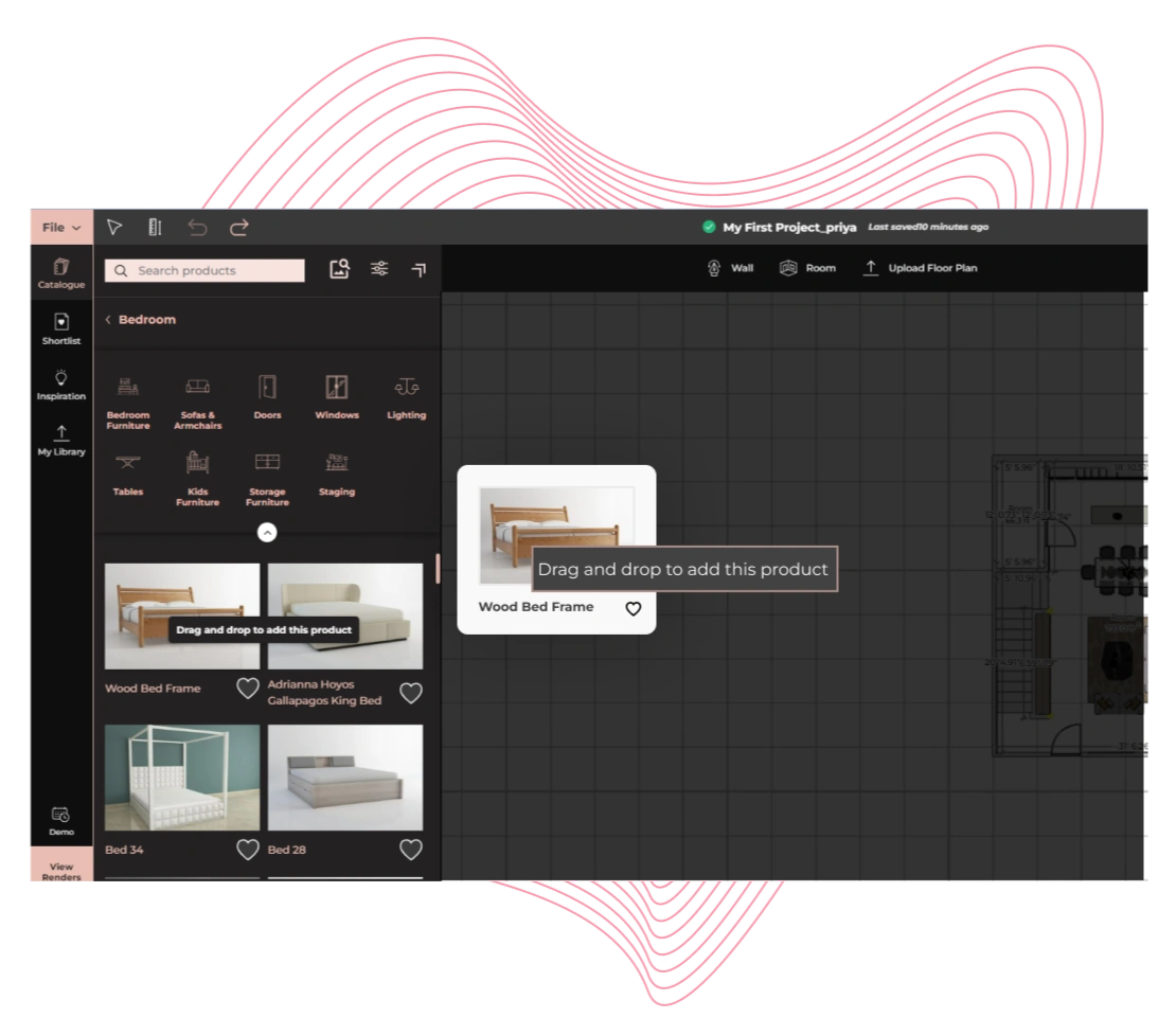
3D Modeling
Stop worrying about 3D models - access 60,000+ ready-to-use products. Just drag - drop one and it to your design.
Need a unique item? Import your models, build from scratch Or get it done for you.

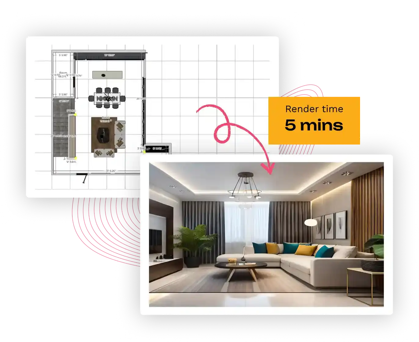
4K Renders & 3D Walkthroughs
Create photorealistic 4K renders and 3D walkthroughs in minutes. Set the shot, select a preset and let AI take care of lighting, shadows and more.
The best part? Rendering is crazy fast. It happens on our servers
Unlike traditional interior design computer programs, Foyr Neo simplifies the process:
Skip the tedious work! Our interior design software app automates time-consuming tasks like floor plan creation, furniture placement, and 3D rendering, helping you design in minutes instead of months.
Try Free For 14 DaysNo Credit Card Or Download Required
No complex CAD software! Whether you’re a beginner or a pro, Foyr Neo’s AI-powered interior decorating software lets you drag, drop, and design effortlessly.
Try Free For 14 DaysNo Credit Card Or Download Required
Forget bulky home design computer software that slows down your system! Foyr Neo is a cloud-based interior design tool, allowing you to render photorealistic visuals without high-end hardware.
Try Free For 14 DaysNo Credit Card Or Download Required
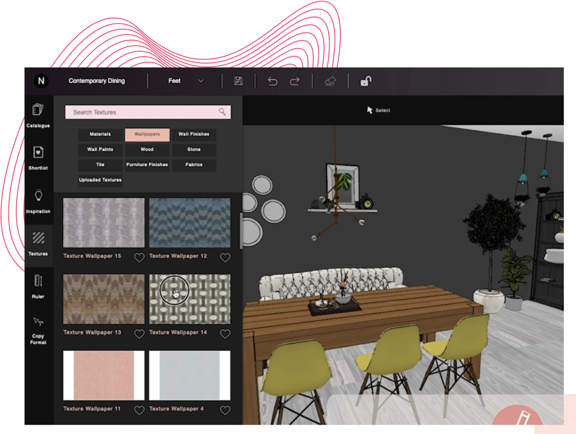
Navigate seamlessly with our AI-assisted interface. Search for design elements, copy-paste textures, and resize objects effortlessly—all in one powerful online interior design tool.
Try Free For 14 DaysNo Credit Card Or Download Required
Access the most extensive collection of design elements among interior decorating apps. Drag and drop from branded furniture, lighting, and decor to create a stunning, professional-grade interior.
Try Free For 14 DaysNo Credit Card Or Download Required
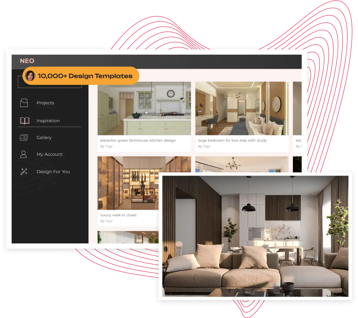
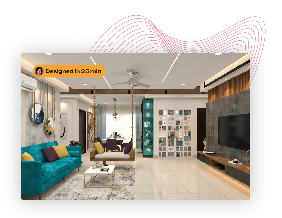
Explore real designs created with our interior decorating app: From minimalist apartments to luxury mansions, Foyr Neo’s design software for interior design brings your ideas to life!

Follow these interior design best practices when designing on professional interior design software, to reap the most benefits and create mindblowing designs for your clients

Organize related objects in your design initially, so you move them together if you plan on placing them elsewhere. You won’t have to grapple with them individually after moving them.
Always visualize the design from all angles possible, and with all lighting conditions – including sunrise, sunset, rainy, wintery, summer, cloudy etc, and in varying intensities so your design is foolproof.
Take a thorough preview, possibly from all camera angles, so you assess every inch of the space before finalizing the rendering design.
Are you fond of a particular texture but unsure if it’ll go well with the design? Download the texture as an image, upload it onto Foyr Neo, and see how it interacts with other materials in the space.
When using professional interior design software like Foyr Neo, leverage Augmented Reality capabilities to find material from the library, customize it, and view how it’ll look in the actual space. This will give you crystal clear clarity on where best to place the product.
Tinkercad accepts standard Arduino C++. While the official Arduino IDE has a popular library, writing a custom lightweight PID algorithm directly in the Tinkercad text editor offers a deeper understanding of how the math translates to code.
You can adapt this code into your Tinkercad Arduino project:
. Since Tinkercad does not support external library uploads, you must implement the PID logic manually or paste the library code directly into the text editor. 1. Essential Components for a PID Circuit
While Tinkercad doesn't have a built-in "PID block," you can write a "deep text" (detailed) script in the Arduino code editor to handle the math. 1. The Core PID Logic tinkercad pid control
The Derivative term estimates the future trend of the error by calculating its rate of change. It acts as a brake. If the system is rushing toward the setpoint too quickly, the derivative term subtracts from the output to slow it down, preventing overshoot. Setting Up the Tinkercad Simulation Circuit
// PID Control Testbed in Tinkercad // Pin Assignments const int setpointPin = A0; // Potentiometer const int sensorPin = A1; // Photoresistor (LDR) const int outputPin = 3; // PWM LED Output // PID Tuning Parameters double Kp = 2.0; // Proportional Gain double Ki = 0.5; // Integral Gain double Kd = 0.1; // Derivative Gain // Core PID Variables double setpoint = 0; double input = 0; double output = 0; double error = 0; double lastError = 0; double cumError = 0; double rateError = 0; // Timing Variables unsigned long currentTime = 0; unsigned long previousTime = 0; double elapsedTime = 0; void setup() pinMode(outputPin, OUTPUT); Serial.begin(9600); void loop() // Read current system state int potValue = analogRead(setpointPin); int sensorValue = analogRead(sensorPin); // Normalize values to a standard 0-255 scale setpoint = map(potValue, 0, 1023, 0, 255); input = map(sensorValue, 0, 1023, 0, 255); // Calculate precise elapsed time currentTime = millis(); elapsedTime = (double)(currentTime - previousTime) / 1000.0; // convert to seconds if (elapsedTime >= 0.05) // Run loop every 50ms for stability // 1. Calculate Error error = setpoint - input; // 2. Compute Integral (Accumulated Error over time) cumError += error * elapsedTime; // Anti-windup protection: Constrain the integral term limit cumError = constrain(cumError, -100, 100); // 3. Compute Derivative (Rate of Error change) rateError = (error - lastError) / elapsedTime; // 4. Calculate Final PID Output Value output = (Kp * error) + (Ki * cumError) + (Kd * rateError); // Constrain output to valid PWM boundaries (0-255) output = constrain(output, 0, 255); // Apply output to the actuator analogWrite(outputPin, output); // Print telemetry to the Serial Plotter Serial.print("Setpoint:"); Serial.print(setpoint); Serial.print(","); Serial.print("Input:"); Serial.print(input); Serial.print(","); Serial.print("Output:"); Serial.println(output); // Save current states for next iteration lastError = error; previousTime = currentTime; Use code with caution. Step-by-Step Tuning in the Simulation
Tinkercad's PID control feature is a great tool for users who want to create and simulate control systems for their designs. While it may not offer advanced features for complex control systems, it is easy to use and provides a great introduction to PID control principles. Tinkercad accepts standard Arduino C++
This comprehensive guide covers the theory of PID control, explains how to build a feedback loop circuit in Tinkercad, and provides optimized code to get your simulation running perfectly. Understanding the Core Concepts of PID Control
double temp_state = 20.0; // ambient start const double ambient = 20.0; const double heatingRate = 0.08; // °C per sec at full power const double coolingTau = 40.0; // larger -> slower cooling
Set Ki and Kd to 0.0 . Increase Kp slowly until the system output starts oscillating back and forth around your setpoint. 2. Isolate the Proportional Term Since Tinkercad does not support external library uploads,
Should we integrate a into your Tinkercad layout to monitor real-time errors? Share public link
This is called Integral Windup . The code includes an anti-windup constraint block to stop this error. Ensure your constrain() limits match your hardware power limitations.
control, allowing users to simulate complex feedback loops without the risk of burning out real hardware. By combining an Arduino microcontroller with sensors and actuators, you can build self-correcting systems like speed-regulated motors or distance-keeping robots entirely in your browser. Core PID Implementation in Tinkercad
As you change the temperature slider, you will observe the lines adjusting dynamically:
PID stands for . It calculates an "Error" (Target Position - Current Position) and uses three terms to calculate the motor output:

Discover how you can Bring your VR Design to life like never before with Foyr! ...
Read article
Discover the art of collaboration between interior designers, contractors, and builders. Learn how t...
Read article
Master pricing strategies for interior designers with Foyr's guide. Learn to set rates, value your s...
Read articleTinkercad accepts standard Arduino C++. While the official Arduino IDE has a popular library, writing a custom lightweight PID algorithm directly in the Tinkercad text editor offers a deeper understanding of how the math translates to code.
You can adapt this code into your Tinkercad Arduino project:
. Since Tinkercad does not support external library uploads, you must implement the PID logic manually or paste the library code directly into the text editor. 1. Essential Components for a PID Circuit
While Tinkercad doesn't have a built-in "PID block," you can write a "deep text" (detailed) script in the Arduino code editor to handle the math. 1. The Core PID Logic
The Derivative term estimates the future trend of the error by calculating its rate of change. It acts as a brake. If the system is rushing toward the setpoint too quickly, the derivative term subtracts from the output to slow it down, preventing overshoot. Setting Up the Tinkercad Simulation Circuit
// PID Control Testbed in Tinkercad // Pin Assignments const int setpointPin = A0; // Potentiometer const int sensorPin = A1; // Photoresistor (LDR) const int outputPin = 3; // PWM LED Output // PID Tuning Parameters double Kp = 2.0; // Proportional Gain double Ki = 0.5; // Integral Gain double Kd = 0.1; // Derivative Gain // Core PID Variables double setpoint = 0; double input = 0; double output = 0; double error = 0; double lastError = 0; double cumError = 0; double rateError = 0; // Timing Variables unsigned long currentTime = 0; unsigned long previousTime = 0; double elapsedTime = 0; void setup() pinMode(outputPin, OUTPUT); Serial.begin(9600); void loop() // Read current system state int potValue = analogRead(setpointPin); int sensorValue = analogRead(sensorPin); // Normalize values to a standard 0-255 scale setpoint = map(potValue, 0, 1023, 0, 255); input = map(sensorValue, 0, 1023, 0, 255); // Calculate precise elapsed time currentTime = millis(); elapsedTime = (double)(currentTime - previousTime) / 1000.0; // convert to seconds if (elapsedTime >= 0.05) // Run loop every 50ms for stability // 1. Calculate Error error = setpoint - input; // 2. Compute Integral (Accumulated Error over time) cumError += error * elapsedTime; // Anti-windup protection: Constrain the integral term limit cumError = constrain(cumError, -100, 100); // 3. Compute Derivative (Rate of Error change) rateError = (error - lastError) / elapsedTime; // 4. Calculate Final PID Output Value output = (Kp * error) + (Ki * cumError) + (Kd * rateError); // Constrain output to valid PWM boundaries (0-255) output = constrain(output, 0, 255); // Apply output to the actuator analogWrite(outputPin, output); // Print telemetry to the Serial Plotter Serial.print("Setpoint:"); Serial.print(setpoint); Serial.print(","); Serial.print("Input:"); Serial.print(input); Serial.print(","); Serial.print("Output:"); Serial.println(output); // Save current states for next iteration lastError = error; previousTime = currentTime; Use code with caution. Step-by-Step Tuning in the Simulation
Tinkercad's PID control feature is a great tool for users who want to create and simulate control systems for their designs. While it may not offer advanced features for complex control systems, it is easy to use and provides a great introduction to PID control principles.
This comprehensive guide covers the theory of PID control, explains how to build a feedback loop circuit in Tinkercad, and provides optimized code to get your simulation running perfectly. Understanding the Core Concepts of PID Control
double temp_state = 20.0; // ambient start const double ambient = 20.0; const double heatingRate = 0.08; // °C per sec at full power const double coolingTau = 40.0; // larger -> slower cooling
Set Ki and Kd to 0.0 . Increase Kp slowly until the system output starts oscillating back and forth around your setpoint. 2. Isolate the Proportional Term
Should we integrate a into your Tinkercad layout to monitor real-time errors? Share public link
This is called Integral Windup . The code includes an anti-windup constraint block to stop this error. Ensure your constrain() limits match your hardware power limitations.
control, allowing users to simulate complex feedback loops without the risk of burning out real hardware. By combining an Arduino microcontroller with sensors and actuators, you can build self-correcting systems like speed-regulated motors or distance-keeping robots entirely in your browser. Core PID Implementation in Tinkercad
As you change the temperature slider, you will observe the lines adjusting dynamically:
PID stands for . It calculates an "Error" (Target Position - Current Position) and uses three terms to calculate the motor output:
Try the fastest interior design software free for 14 days!
Try Free For 14 Days No credit card required – Just start designing!